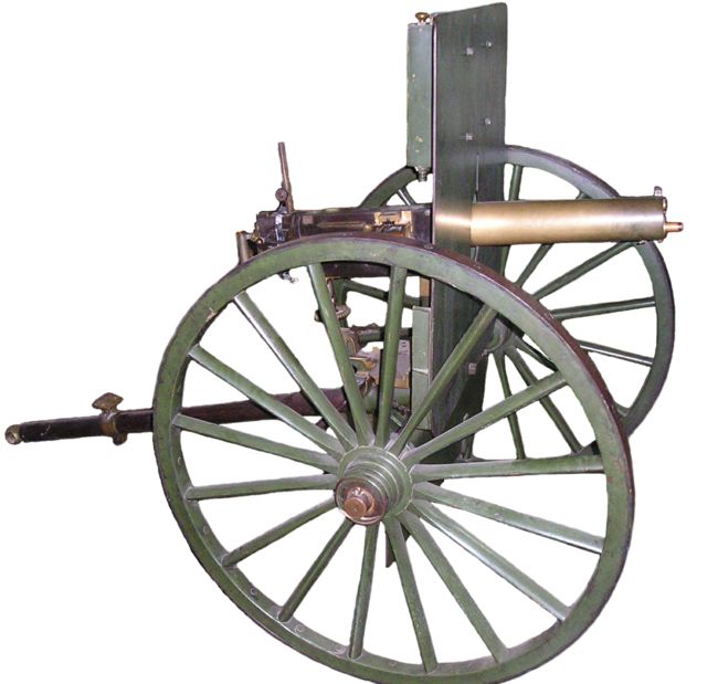
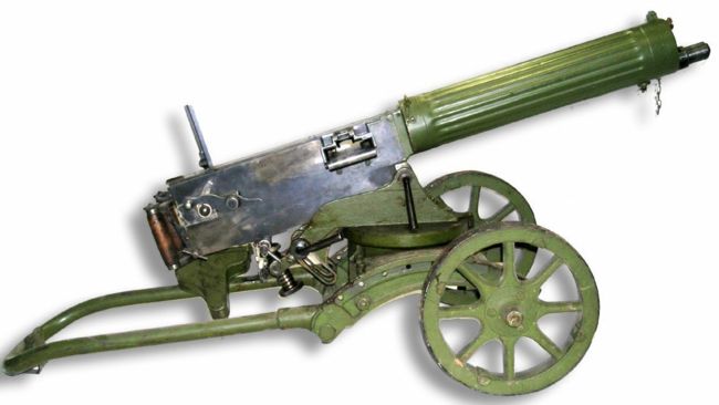
19th-century production4.2 line (.42inch – 11mm, blackpowder) Russian Maxim machine gun on artillery-type mount.
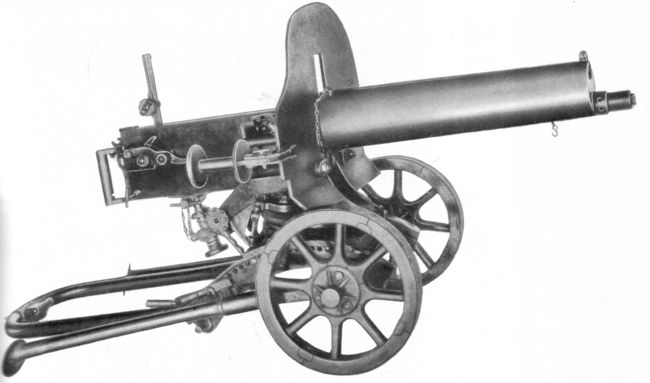
7.62mm Maxim M1910 machinegun on original Sokolov type wheeled mount with shield and folded legs.
7.62mm Maxim M1910 machinegun on original Sokolov type wheeled mount with shield and legsextended to provide higher line of fire.
7.62mm Maxim M1910-30machine gun on simplified Sokolov mount without folding legs; shield removed to save the weight.
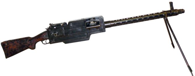
Maxim-Tokarev light machine gun, as produced between 1925 and 1928.
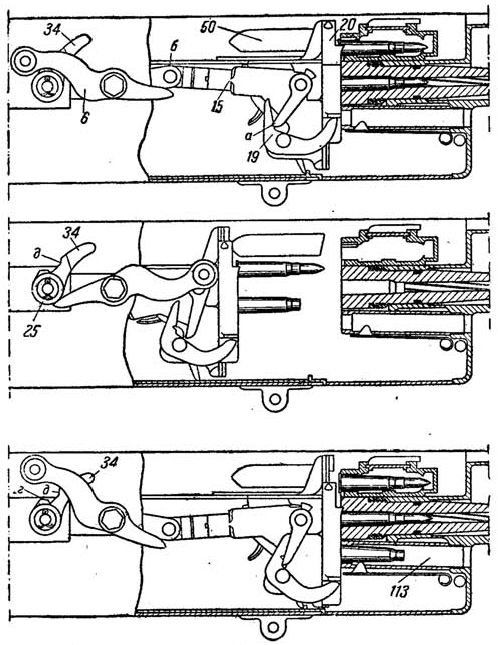
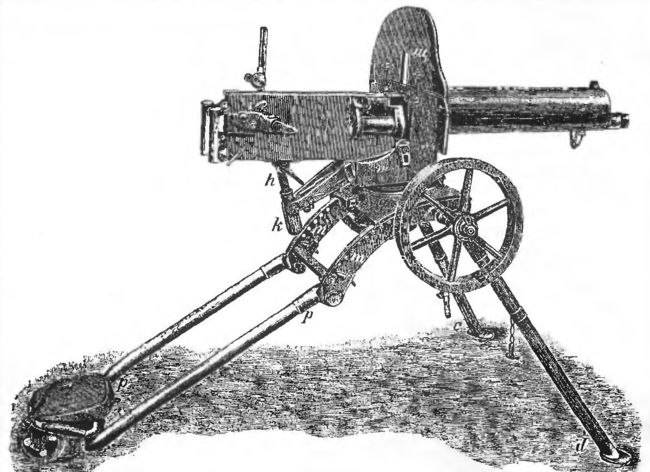
Diagram of the Maxim-typetoggle-lock action and feed.
| Maxim M1910/30 | Maxim-Tokarev | |
| Caliber | 7.62x54R | 7.62x54R |
| Weight | 20 kg (gun less water) + 43 (Sokolov mount with shield) | 12.9 kg (with bipod) |
| Length | 1070 mm | 1330 mm |
| Barrel length | 720 mm | 655 mm |
| Feed | belt, 250 rounds | belt, 100 or 250 rounds |
| Rate offire | 600 roundsper minute | 600 roundsper minute |
The typical Maxim machine gun is short recoil operated, water cooled, full automatic only belt-fed machine gun. All Maxim guns fired from closed bolt, which was not a problem for water-cooled guns. Early guns had barrel water jackets made from polished bronze; later on, these were replaced with steel jackets,usually painted with khaki paint.
The basic toggle-lock action,patented by Hiram Maxim, used two struts, connected by the hinge, and located between the breech block and a barrel extension in such a manner that when breech block was in battery, struts formed a straight line and transferred the pressure, exerted by the hot powder gases through the base of the cartridge, directly to the barrel extension.This caused the entire barrel / extension / breech block group to recoil inside receiver, against the tension of the spring, located under the separate cover outside of the left receiver wall. After short recoil, the cocking handle, which was located on the rear axis of the toggle system, struck the pin installed on the right receiver wall.This caused the cocking handle to rotate up and forward, thus breaking the toggle down. The cocking handle served as both unlocking member and a breech block accelerator, as its shape caused the toggle to open rather fast. During the opening movement of the breech block, the empty cartridge was extracted from the barrel, and the separate breech face,with integral T-slot that held the cartridge case by its rim, was slid downward, to put the fired cartridge case below the barrel and in alignment with short extraction tube, that was located under the barrel and emerged from the front of receiver. At the same time, the fresh cartridge that was picked by the T-slot during the previous cycle, was lowered and put in line with the chamber. The closing movement of the toggle was controlled by the return spring, located on the left side of the receiver. Unlike most other weapons, the return spring was extended during the recoil, rather than compressed; it was attached to the pivoting lever, located co-axially with cocking handle on the rear toggle axis. Thus, upon counter-recoil cycle, this spring forced the toggle to straighten up from its bent position, pushing the breech block (with fresh cartridge above and fired case below both held in in the T-slot) forward, and entire barrel / breech block system into the battery. Upon final part of closing movement of the bolt, the sliding breech face was risen up, to leave spent cartridge in the ejection tube and to catch the next fresh cartridge from the belt by its rim. If the trigger was still pushed, the firing pin was released by the trigger ling, which engaged the sear, built into the breech block. The trigger itself was located between dual spade grips, at the backplate of receiver; it was pushed by thumbs.
The feed system used non-disintegrating belts, made from cloth or tarpaulin, with metallic struts. Feed was from the right side only; feed system was operated through the horizontally pivoting pin / levers system by recoiling barrel group. Early Maxim guns featured feed blocks made from brass;later on, less expensive steel feed blocks were substituted.
Over the time, there was a great variety of mountings, produced for Maxim guns in many countries; earliest mountings were of “artillery” type,with large wheels, armored shields and long trailing booms. Later on,most armies adopted a number of more convenient tripods, which were lighter, less expensive, and offered less target silhouette for enemy fire.
The most typical feature of the Russian Maxim guns was the wheeled mount with armoured shield. The mounts were of two basic patterns, one designed by Sokolov by 1910, and another designed by Vladimirov by 1939. The Sokolov mount was intended for fire against ground targets only, and was built in several versions with minor differences. It was characterized by the U-shaped tail which was used to drag the mounted gun through the battlefield on its own wheels. The earliest versions of the Sokolov mount had additional folding legs which allowed the gun to be raised above the ground, but this was soon found impractical and these legs were omitted in later versions of the mount. The U-shaped tail can be folded down and forward, when the gunis to be fired from a trench. The Vladimirov mount was intended for both ground fire and anti-aircraft use; it had a folding tripod with adetachable two-wheeled base. In “ground application” mode gun was fired from its wheels (similar to the ones of the Sokolov mount), and the three legs of the tripod formed a single boom-shaped tail for the mounting. In AA applications the wheeled base was detached and the legs unfolded to form a tripod. While all infantry Maxim guns were issued with armoured shields, troops often discarded these in order to lighten the gun (shield weighted about 11 kg) and made it less noticeable on the battlefield.
While the basic mechanism of the Maxim gun remained the same throughout its entire production life in Russia and the USSR,several improvements were made, such as an improved belt feed unit of simplified manufacture (made from cast steel or aluminum rather than machined from steel or bronze). There were two basic types of feed unit– one that allowed the use of cloth belts only, and a universal feed that allowed for the use of both cloth and steel (non-disintegrating)belts. The new universal feed block was manufactured from aluminum alloy. Other modifications included sighting equipment; first, some guns were fitted with a special sight mount on the left side of the receiver which allowed quadrant or telescopic sights to be mounted,intended mostly for indirect fire applications. Such guns were also issued with modified shields with windows for sighting. The standard adjustable rear iron sight was first upgraded in 1930 with the addition of a second range scale (for the newly adopted heavy bullet loading)and with a windage-adjustment mechanism. During the war, the second scale was abandoned as a minor cost-saving feature, because for ranges up to 1000 metres the trajectories of both light and heavy bullets were close enough, and in the new tactical doctrine it was not recommended to fire medium MGs at ranges beyond 1000 metres. The 1930 upgrade also included a more convenient thumb safety under the trigger, a swing-openrear receiver cover, and a ribbed barrel jacket (for added strength and a larger cooling area). During the war, however, barrel jackets were often made plain, without ribbing, as another cost-saving measure.
Asa result of the Winter War (1940) with Finland, newly made Maxim M1910/30 guns were modified with a larger water-filling port on the jacket, to allow a faster refill and also to permit snow instead of water to be used (a feature borrowed from Finnish Maxims).
Other than the aforementioned Sokolov and Vladimirov mounts (which were manufactured simultaneously and concurrently between 1939 and 1945),the third most popular mount was the Tokarev-designed quad AA mount,used for fixed installations and also often mounted on trucks to provide mobile AA defence. These mounts were manually operated, and used larger ammunition boxes that held 500 rounds (instead of standard 250-round belt boxes), with provision for steam condensers and with ring-type AA sights.
Modifications:
Maxim-Tokarev (M-T) light machine gun:This was an interim “light machine gun” modification, built along the lines of the German lMG 08/18 light machine gun. Water jacket was discarded and replaced by thin perforated steel jacket, and the barrel was shortened and lightened. Barrel could be changed more or less quickly in the field. Spade grips were replaced with rifle-type stock;thumb-trigger was replaced by rifle-type trigger. Folding bipod was attached to the barrel jacket.
Feed system was the same as onM1910 Maxim guns, except that standard belt capacity was reduced to 100 rounds (original 250-round belts also could be used in M-T). 100-roundbelts were usually carried in separate drum-type containers.
About 2500 Maxim-Tokarev guns were produced by Tula arms factory (TOZ) in 1926-27; many were later sold to Republican Spain.

Encyclopedia of firearms and ammunition of the XX and XXI centuries
All texts are written by Maxim Popenker © 1999-2026

